
| Attrezzatura | Nome | Inventario n. | Note/Info |
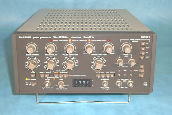
| Fluke Pulse Generator | PM5786B | 6160 | FLUKE |
Fluke Pulse Generator PM5786B – FLUKE-PM5786B-Datasheet
 |
Time parameters
Main pulse characteristics
corresponding to 10% and 90% of pulse amplitude. For ECL testing the minimum transition time is 1.4ns corresponding to 20% and 80% of pulse amplitude. Pulse amplitude 0.2V… 5V (at ZL = 50 Ω), double amplitude at open output, within the range ±6V.
Maximum 10V open output amplitude can be achieved provided the signal is in the range ±6V. Waveform aberrations
(lHz… 1MHz); 50% ±10% (1MHz… 125MHz) Normal or complementary, switchable. Output modes
External operating modes
TRIGG Externally triggered pulserepetition DC… 125MHz or manual single shot.
selection of number of pulses 0…9999, started by external input signal or manual control. EXT DUR External duration gives pulses with same duration and repetition rate as external input signal, all other pulse parameters are set via the generator. External input
< 440Hz, declining to 15Vpp at 125MHz. Internal clock output
Main output pulse is delay-able with respect to internalclock output, which therefore can be used as pre-trigger.
transition times, indicated with 4 LED’s. General Specification
|
| Line | 100V, 120V, 220V and 240Vrms ±10%. 120VA, 50…60Hz. According to CE-regulation |
| Safety |
Pollution Degree 2 and
CSA 556B.
Electromagnetic
| Compatibility (EMC) | According to CE-regulation 89/336 |
550081-1, EN 55022 Class
B, EN 60555
Immunity according to EN
50082-1, inclusive IEC
801-2,-3,-4-5
Environmental conditions
Temperature– Operating 0°C…+50°C.
– Storage -40°C…+70°C.
Humidity
– Operating 10…90% RH,
non-condensing.
– Storage 5…95% RH.
Altitude Barometric pressure
– Operating 5000m (15000ft)-
53.3kN/m2.
– Storage 15000m (50000ft)-
15.2kN/m2.
Dimensions and weight
– Height 145mm ( 5.7in)– Width 300mm (11.8in)
– Depth 470mm (18.5in)
– Weight Net 9.5kg (2lLb)
| – Weight Shipping Included with instr. |
11.5kg (25Lb) Manual, power cord |