- The bottom anodized Aluminum plate (0.5 mm) is positioned inside the Teflon fixture. This plate will be in contact with the lower target section T1
(picture below)
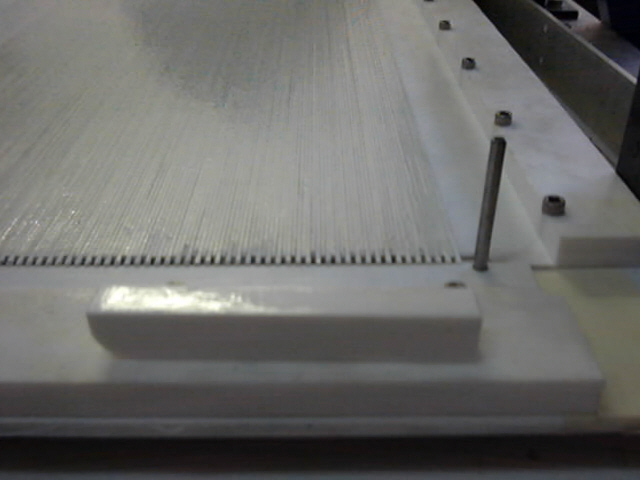
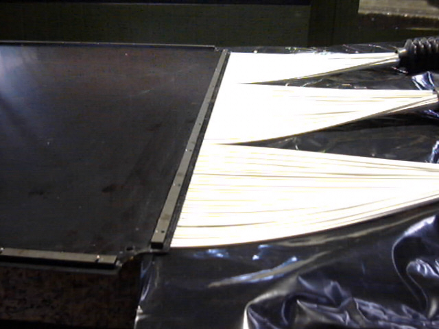
- Fibers are being aligned into the alignment fixture. The fibers staggering (5 mm) on either end is visible at the bottom of the picture. Scintillating fibers are closely packed during the glueing.
(picture below)
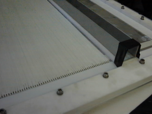
On the left of the picture, one 0.2 thick Al plate (not anodized) is visible where the scintillanting fibers are being glued on. Each scintillator layer is sandwiched between an outer 0.5 mm thick Al plate and an inner 0.2 mm thick Al plate.- The two orthogonal layers are mounted on top of each other with the two 0.2 mm plates glued together. The total thickness is therefore : 0.5 + 2.2 + 2*0.2 + 2.2 + 0.5 = 5.8 mm approx.
(picture below) - The two orthogonal layers are mounted on top of each other with the two 0.2 mm plates glued together. The total thickness is therefore : 0.5 + 2.2 + 2*0.2 + 2.2 + 0.5 = 5.8 mm approx.
- Make sure nothing moves until the glue has cured !
(picture below)
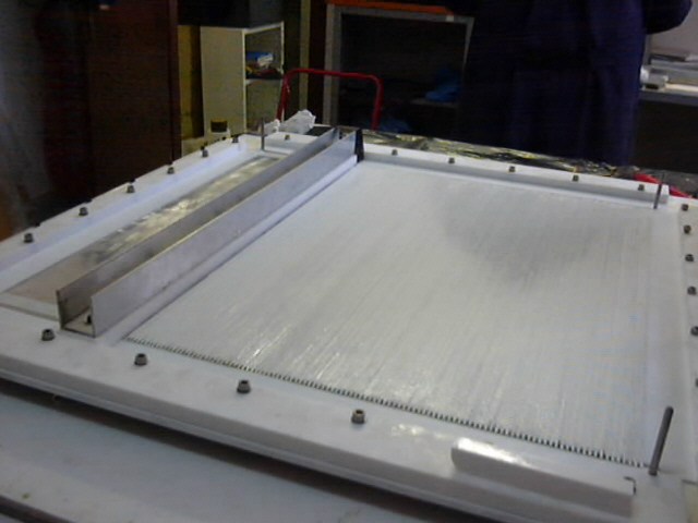
- The scintillating fibers are now glued onto the 0.2 mm thick Al plate.
(picture below)
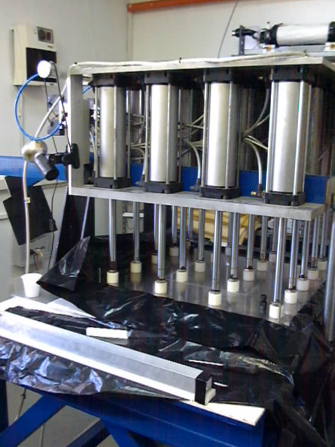
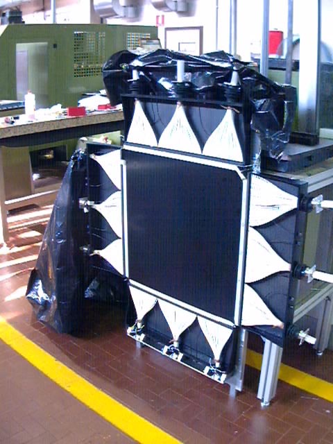
- The light-tight boxes are being assembled
(picture below)
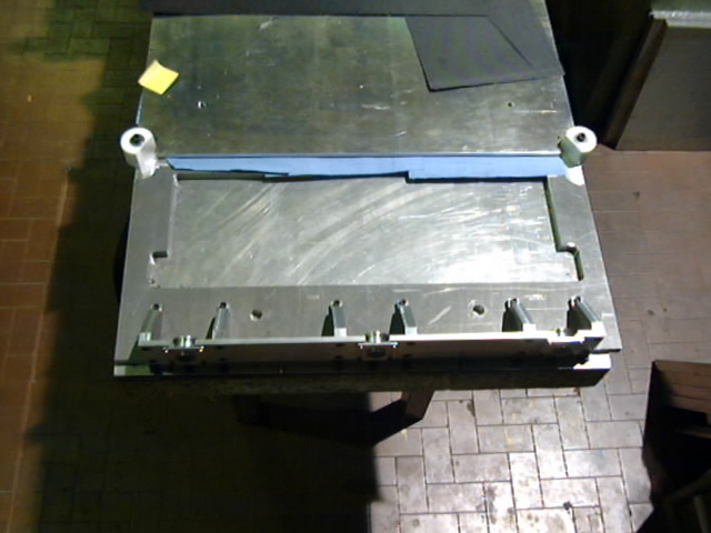
- The alignment fixture used to accurately position the HPD cookies w.r.t. precision pins where the scintillator planes are aligned to.
(next 2 pictures)
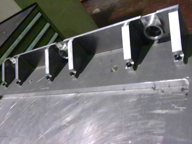
- The clear-fibers are glued head-on to the scintillating fibers. The glue-joint is not visible in the picture, being covered by the 1mm thick Al plate which is glued on top of the scintillating fibers plane and overlaps the glue-joint completely.
(picture below)
- Clear fibers are first stuffed into the HPD cookies and then glued. The picture shows 3 clear fibers bundles being glued into the 3 PMT cookies nearest to the floor.
(picture below)
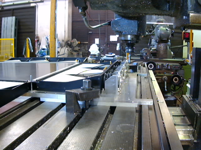
- The optical interface of the HPD cookies is being milled prior to polishing. This operation is repeated on the each of the 4 faces of S2. Precision alignment pins are used to position the coupled scintillator planes onto the alignment fixture. The final precision on the distance between the respective optical interfaces of 2 HPDs on opposite sides of S2 relies on the alignment fixture accuracy.
(picture below)
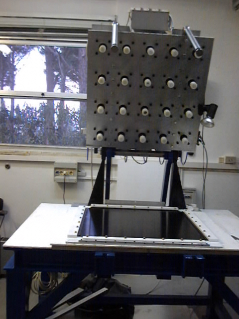
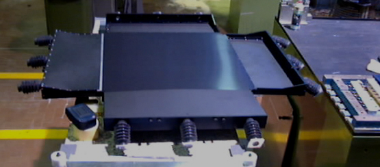
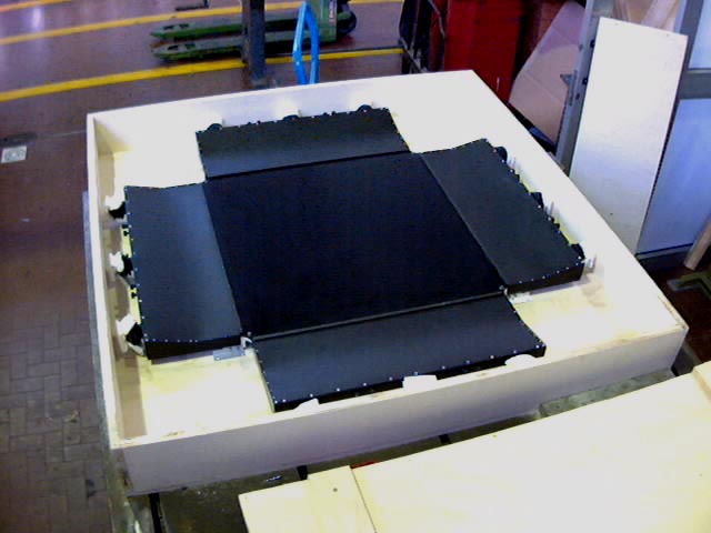
- S2 in its wooden crate after assembly and before shipping to Cern
(picture below)
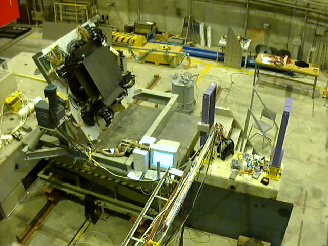
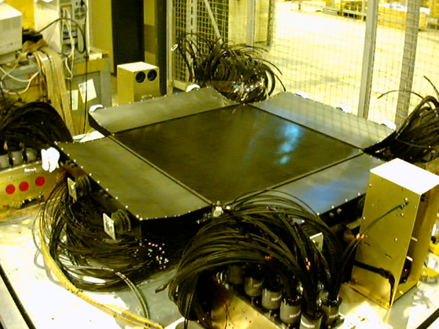
- The S2 hodoscope is being installed on top of the lower half of the target (T1) at Cern (July 2002)
(picture below)
- S2 after installation in between the two target sections T1 and T2 at the CERN beam H2 (July 2002)
(picture below)